Tool

- Tool Notice: Undefined offset: 2 in /home/host/gb/www/html/_skin/layout/inc_navigation_middle.php on line 60 Notice: Undefined offset: 2 in /home/host/gb/www/html/_skin/layout/inc_navigation_middle.php on line 87 Notice: Undefined offset: 3 in /home/host/gb/www/html/_skin/layout/inc_navigation_middle.php on line 87
Tool
GB Tools
GB manufactures the widest range of high quality demolition tools in Korea, compatible with most hydraulic heavy duty breakers. Engineers at GB are doing their best in manufacturing process, quality control and R&D to produce the highest quality demolition tools in the world.
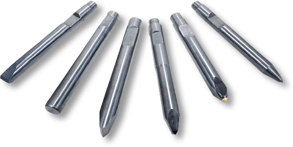
Tool Code Description
| Shape | Type | Code | Application | |
|---|---|---|---|---|

|

|
CHISEL | CH |
NON-ABRASIVE BUT DUCTILE ROCK
|

|

|
MOIL | MO |
SOFT, NON-AERASIVE ROCK
|

|

|
CONE | CO |
SOFT, NON-AERASIVE ROCK
|

|

|
BLUNT | BL |
SOFT OR HARD
|
- GB Tools are guaranteed against defects in material and manufacturing.
- The liability of GB with respect to any warranty claims is limited to tools replacement and does not extend to any other incurred expenditure or to consequential damage.
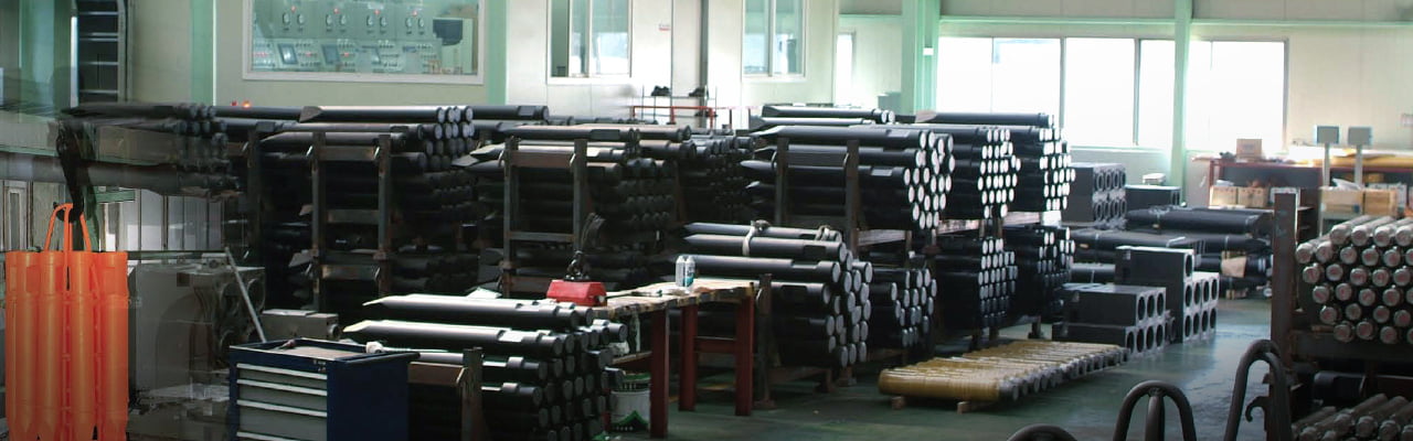
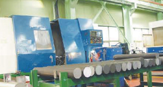
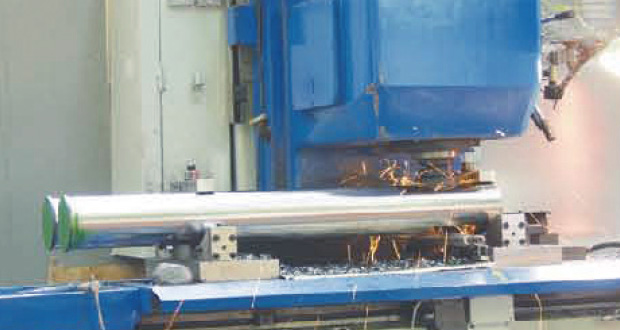
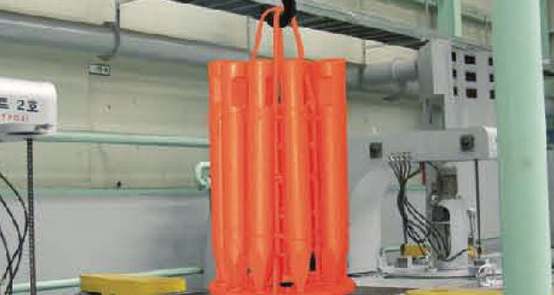
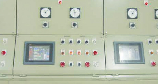
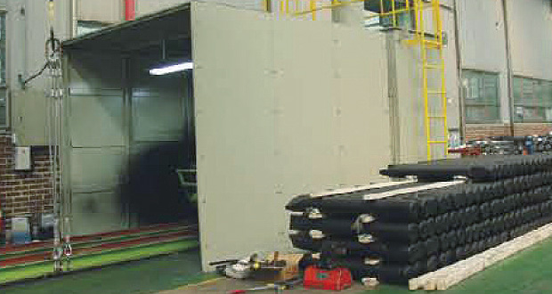
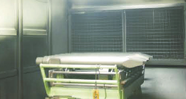
Manufacturing & Quality Control Process
Tool Claim Warranty Guide
The purpose of this guide is to enable you to show your customer the correct application of GB Tools and to assist you in resolving complaints immediately when they occur. When a tool has apparently failed to give satisfactory service life, a visual inspection often resolves the cause quickly and saves transport costs and frustration when warranty is rejected.
How a Demolition Tool Breakers Rock and Concrete
When the hammer (breaker) piston strikes the top of a demolition tool, it sends a compressive stress wave down to the working end of the tool.
Provided the demolition tool is in contact with the rock or concrete which requires breaking, it is this compressive stress wave which fractures the rock. Immediately following the compressive stress wave, a tensile stress wave is formed due to the hammer piston lifting from the top of the demolition too!
This cycle of compressive and tensile stresses flowing down the to of repeated for each hammer blow. Obviously, anything that interferes with the 'strength' if the compressive stress wave during service, for example 'free running' or bending of the demolition tool due to leverage will result in loss of breaker effciency of up to 80% and possible fatigue failure of the tool itself.
-
01
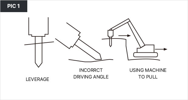
The main cause of increased fatigue stress in a demolition tool is any form of side pressure during service which creates bending. Thus utilizing the tool as a lever, using the incorrect driving angle or attempting to break ground using the pull of the machine are all detrimental to the life of a demolition tool and should be avoided. (see PIC 1)
02
Other causes of increased fatigue stress in a demolition tool include.
A) 'Free running'
In general this is any situation where the hammer piston strikes the top of the demolition tool, but the working end is not in proper contact with the rock or concrete to be broken. This includes jobs where the tool slides off the work and also when breakthrough of thin concrete slabs or boulders occurs.- B) Cold
- Low temperature causes a demolition tool to be more susceptible to fatigue failure.
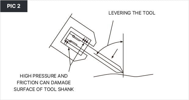
Tools should be warmed before use. - C) Mechanical and thermal damage
- Any form of damage to the surface of a demolition tool renders it more liable to suffer fatigue failure.
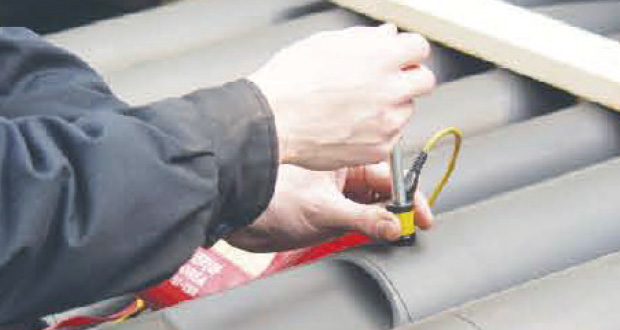
Thus all care must be exercised to prevent accidental gouging, or contact welding ('galling' or 'pick-up') due to contact between the tool and chuck bushing through the lack of lubrication or excessive leverage. (see PIC 2) - D) Lubrication
- Care must be taken to avoid metal to metal contact that, as a result of galling or pick-up, could cause deep damage marks which, in turn, lead to the formation of fatigue cracks and eventual failure of the demolition tool. Ensure that the shank of the demolition tool is well lubricated before locating in the machine. Molybdenum bisulphide grease is recommended for this application at three hourly intervals or as per manufactures instruction.
- E) Corrosion
- A rusty demolition tool is more likely to suffer fatigue failure, thus keep tools well greased and sheltered from the weather when not in use.
-
03
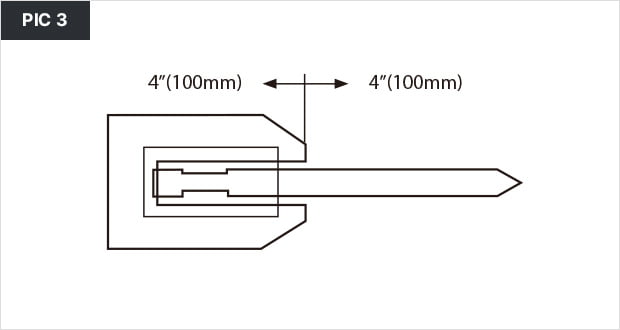
A demolition tool fatigue failure will generally occur approximately 4" (100mm) either side of the chuck front face
(see PIC 3)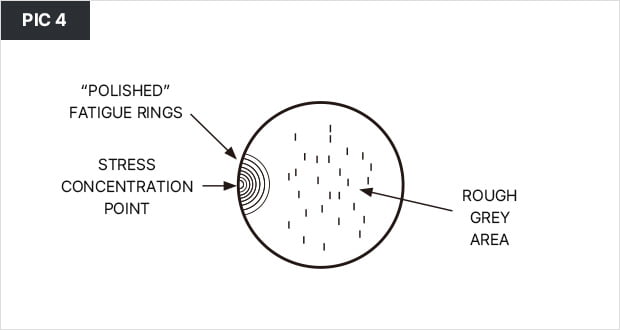
04
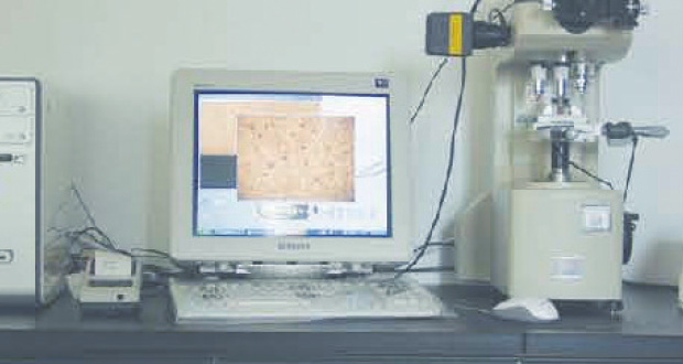
Another slightly less common failure area can fall approximately 8"(200mm) from the working end, subject to nature of use.
The fracture face itself will normally exhibit a semi-circular polished area with the remainder being of a rougher appearance
(see PIC 4)- The polished semi-circular area in pic4 isthe fatigue area and generally startsfrom a damage mark or otherstress raisers on the outside of the demolition tool and spreads inwards. The fatigue area slowly widens until the stresses being applied to the demolition tool cause sudden failure of the remaining section. Generally, the size of the fatigue area indicates the level of stress applied to the tool, i.e. the smaller the fatigue area, the higher the stresslevel, although it must be borne in mind that once initiation of a fatigue crack hastaken place, it requires a lower stress level to cause it to grow.
-
05
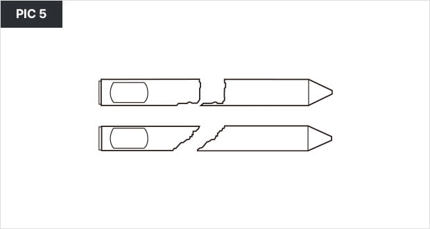
Typical fractures caused by excessive bending of the demolition tool.
Warranty claims rejected.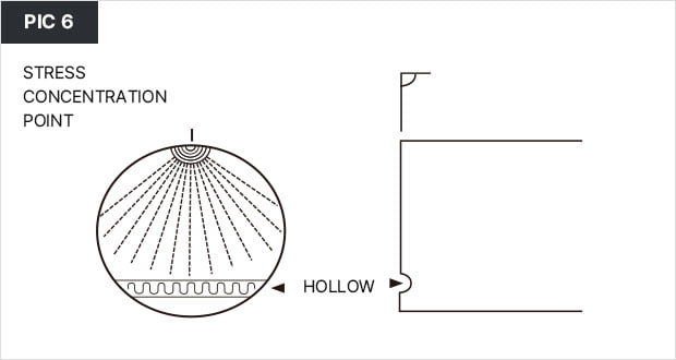
06
Typical of high stress fracture, usually caused by using the machine to "pull".
Warranty claims rejected.